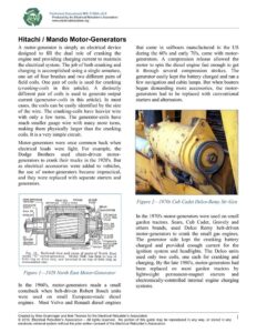
Technical Document MS-1108A-v2.0 Produced by the Electrical Rebuilder’s Association www.electricalrebuilders.org Hitachi / Mando Motor-Generators A motor-generator is simply an electrical device designed to fill the dual role of cranking the engine and providing charging current to maintain the electrical system. The job of both cranking and charging is accomplished using a single armature, one set of four brushes and two different pairs of field coils. One pair of coils is used for cranking (cranking-coils in this article). A distinctly different pair of coils is used to generate output current (generator-coils in this article). In most cases, the coils can be easily identified by the size of the wire. The cranking-coils have heavier wire with only a few turns. The generator-coils have much smaller gauge wire with many more turns, making them physically larger than the cranking coils. It is a very simple circuit. Motor-generators were once common back when electrical loads were light. For example, the Dodge Brothers used chain-driven motor- generators to crank their trucks in the 1920’s. But as electrical accessories were added to vehicles, the use of motor-generators became impractical, and they were replaced with separate starters and generators. CORK RETAINING FIELD coi. «= TIE ROD 10 AMP. WASHER ARMATURE | FIELD RING FUSE ARMATURE SHAFT y) Nan blll BPs ote ~ PE Ciiavimia ee a a ‘c % pe Siw ¢ CRIMPED a ii /AnanERRERIS;| Jt BRUSH *SR&BRUSH SPACER rr HOLDER BRUSH HOLDER— SRUSH STyD Fig. 13. Sectional view and name of parts of North East model ‘‘G’’ motor-generator. Model (GA) has fuse in top of field ring at drive end, and terminal is on top of field ring at commutator end. Figure I—1928 North East Motor-Generator In the 1960’s, motor-generators made a small comeback when belt-driven Robert Bosch units were used on small European-made diesel engines. Most Volvo and Renault diesel engines that came in sailboats manufactured in the US during the 60’s and early 70’s, came with motor- generators. A compression release allowed the motor to spin the diesel engine fast enough to get it through several compression strokes. The generator easily kept the battery charged and ran a few navigation and cabin lamps. But when boaters began demanding more accessories, the motor- generators had to be replaced with conventional starters and alternators. Figure 2—1970s Cub Cadet Delco-Remy Str-Gen In the 1970’s motor-generators were used on small garden tractors. Sears, Cub Cadet, Gravely and others brands, used Delco Remy belt-driven motor-generators to crank the small gas engines. The generator side kept the cranking battery charged and provided enough current for the ignition system and headlights. The Delco units used only two coils, one each for cranking and charging. By the late 1980’s, motor-generators had been replaced on most garden tractors by lightweight permanent-magnet starters and electronically-controlled internal engine charging systems. Created by Wes Grueninger and Bob Thomas for the Electrical Rebuilder’s Association © 2010, Electrical Rebuilder’s Association — All rights reserved. No portion of this guide may be reproduced in any way, or stored in any electronic retrieval system without the prior written consent of the Electrical Rebuilder’s Association. Technical Document MS-1108A-v2.0 Produced by the Electrical Rebuilder’s Association www.electricalrebuilders.org Then in the late 1980’s, gasoline-powered golf carts brought back the motor-generator yet again, with a belt-driven Hitachi unit. By the 1990’s these carts had found their way off the fairways as consumers discovered all kinds of uses for them. It wasn’t long before they started showing up in rebuilding shops for repair, where they caused some confusion, because they have two armature terminals and three field terminals. Today, Mando manufactures a motor-generator that is identical to the Hitachi unit. This article will deal specifically with the most common Hitachi/Mando unit. But remember, all motor-generators operate basically the same way. Figure 3—Hitachi Motor-Generator GSB107-01 Terminals Explained (Figure 3) What Hitachi has done is isolate both the armature and the field circuits from each other and from ground. e Terminals Al and A2 are connected to the armature via two pairs of brushes. e Terminals F1 and F2 are connected to each end of the cranking-coils. e Terminal DF is connected to one end of the generator-coils. e The other end of the generator-coils is connected to F1 internally. e On most applications, Fl and A2 are connected externally using a 6 or 8-gauge jumper cable, as shown in the diagrams and photo. Internal Connection – F1 to Generator Coil Red Wire Figure 4—Internal Generator-Coil Connection Created by Wes Grueninger and Bob Thomas for the Electrical Rebuilder’s Association © 2010, Electrical Rebuilder’s Association — All rights reserved. No portion of this guide may be reproduced in any way, or stored in any electronic retrieval system without the prior written consent of the Electrical Rebuilder’s Association.