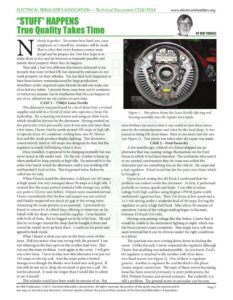
ELECTRICAL REBUILDER’S ASSOCIATION — Technical Document CS201705A www.electricalrebuilders.org “STUFF” HAPPENS True Quality Takes Time obody is perfect. No matter how hard you, your employees or I myself try, mistakes will be made. That is a fact that every business owner must accept and be prepare for. Our best hope is to make them as few and far between as humanly possible and handle them properly when they do happen. That said, I had two different alternators delivered to me recently that were verified OK but claimed by end users to not work properly on their vehicles. The fact that both happened to have been factory remanufactured by large production rebuilders under respected name brands should not make any of us feel any better. I present these cases here not to condemn or embarrass anyone, but to emphasize that this can happen to any of us, whenever we cut corners to save time. CASE 1 – 7706JA Leece Neville This alternator was purchased by a local shop from a trusted supplier and sold to a friend of mine who operates a Snap-On dealership. He is nearing retirement and using an older truck, which should be obvious by the alternator. Having worked on this particular truck personally since it was new and more than a few times, I know that he needs around 100 amps at high idle to operate three AC condenser cooling fans, two AC blower fans and the inside product display lighting. This alternator, conservatively rated at 165 amps was designed do that, but the regulator is nearly full fielding when it does. Once installed, it appeared to be charging normally but was never tested at idle under load. On the job, it failed to keep up when parked for long periods at high idle. He returned it to the seller who bench tested the alternator, said it was working OK and handed it back to him. This happened twice, before he called me for help. When I bench tested the alternator, it did put out 165 amps at high speed, but only managed about 50 amps at a high idle. I noticed that the scope pattern looked a little strange too, unlike any pattern I’d ever seen before. Output noise sounded normal. I knew immediately that the low end output was not normal and frankly suspected too much air gap or the wrong rotor, dismissing the scope pattern as an anomaly. I pressured my friend to return for it a third time, offering to intervene on his behalf with the shop’s owner and his supplier. I was familiar with both of them. But he begged me to fix it for him. He said that he no longer trusted the shop that he bought it from and vowed he would never go back there. I could see his point and agreed to look inside. What I found is what you saw on the front cover of this issue. Did you notice what was wrong with the picture? Iam not referring to the bare spot on the rectifier lead wire. That was not the main problem. Look again at the cover. I will give you a few hints. I have no idea how this alternator ever put out 165 amps on the top end. And the scope pattern looked strange even though the diodes were brand new and good. If you still do not see it, drop me an email or give mea call. Do not be ashamed. It took me longer than I would like to admit to see it myself. 4… __ BY BOB THOMAS Figure 1 – This photo shows the Leece Neville slip ring end housing assembly once the repairs were made. what bothers me most is that it was tested at least three times, once by the remanufacturer and twice by the local shop. It was passed as being OK three times. Here is one more hint for you (see Figure 1). That photo was taken after the repair was made. CASE 2 – Ford Focus 6G A few months ago, a friend of a friend shipped me an alternator that was causing voltage fluctuations on the Ford Focus in which it had been installed. The technician who sent it to me wanted confirmation that the issue was within the alternator and not something else on the vehicle. He suspected a bad regulator. It had tested fine for the parts store from which he bought it. Upon bench testing this 6G Ford, I confirmed that the problem was indeed inside the alternator. At first, it performed perfectly at various speeds and loads. I was able to adjust voltage both high and low using Regitar’s PWM (pulse width modulated) signal test box. Then I let it run at low speed and a 14.5 volt setting under a moderate load of 50 amps, forcing the regulator to carry a high field load. After about 10 minutes of operation, I noticed the voltage reading began to fluctuate between 15.0 and 15.6 volts. Having seen pulsing voltage like this before, I knew that it would be visible in the instrument lighting at night, which was the Focus owner’s exact complaint. That single extra volt may seem minimal but it can be obvious under the right conditions to a driver. The question was now coming down down to finding the cause. Unlike the tech, I never suspected the regulator although I knew that anything was indeed possible. As you know, Ford’s 6G regulator is attached to the rectifier with three 4mm torx-head screws (see Figure 2). One of them is regulator ground. Another is regulator B+ and the third is the phase (stator output) connection. The topic of these screws becoming loose has been covered previously in print publications, the ERA Website Forums and several seminars. But evidently it is This mistake could have been made by anyone of us. But still a problem. The ground screw in particular can become An ERA Publication. ©2017, Electrical Rebuilder’s Association. All rights reserved. No portion of the guide may be reproduced in Page 1 any way, or stored in any electronic retrieval system without the prior written consent of the Electrical Rebuilder’s Association.