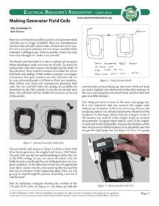
ELecTRICAL REBUILDER’S ASSOCIATION – CS201301A www.electricalrebuilders.org Making Generator Field Coils Wes Grueninger Sr. Bob Thomas Have you ever found yourself in need ofa set of generator field coils that are no longer available? There are manufacturers out there that will still custom make a brand new set for you. It is not a low price solution, but it is always available if the customer is willing to pay. There is another choice you may never have thought of—make a set yourself! We should note here that it is best to exhaust all resources before deciding to make your own set of coils. To search for replacement coils, first measure the length and the width of the pole shoes. Then, look for a similar set in either the Ace or IPM field coil catalogs. While neither company is no longer in business, their part numbers are alive and well and can be cross referenced easily to Wilson or Dixie part numbers. Both Wilson and Dixie still manufacture generator field coils. The Ace and IPM field coil catalogs are available for download on the ERA website if you do not already have them. You will find a full list of field coil resources at the end of this article. Figure 1—Burned Generator Field Coils The set of field coils shown in Figure 1 is from a Delco 036] three-brush generator, the original unit from a 1936 Buick. The pole shoe size did not match anything in either the Ace or the IPM catalog. As you can see in the photo, they are badly burned, even though the rest of the generator is in very good condition. At the end of this article we will explain the most likely reason why the coils ended up like this and the best way to prevent it from happening again. First, we will go step-by-step through the process of winding a new set of coils by hand. Start by sketching a diagram showing the position of the CW and CCW coils (see Figure 2). Lay them out with the An ERA Publication. © 2013, Electrical Rebuilder’s Association. All rights reserved. No portion of the guide may be reproduced oust Deco GevenastoR 936T 6 voer 19 GAveE WIRE 1So Teens) PER CoOL u a Pote SHog A3″L- 1é”w – +34 H Figure 2—Hand-Drawn Sketch curved inside surfaces facing up. Also note which coil leads are joined together and where each of the other leads go. In this case, one lead goes to the third brush, and the other lead goes to a field terminal. One thing you need to know is the exact wire gauge size. It is very important that you measure the copper only, without any insulation. In this case, it was easy, because the insulating enamel was already burned away. Removal of the insulation by burning is better than by trying to scrape it off, because you need all of the copper to get an accurate measurement. Scraping might remove some of the copper. A torch will do this job quickly. Measure the thickness of the bare wire in several different places to be absolutely sure that you get the right gauge size (see Figure 3). Use a wire gauge Figure 3—Measuring the Wire O.D. Page | in any way, or stored in any electronic retrieval system without the prior written consent of the Electrical Rebuilder’s Association. ELECTRICAL REBUILDER’s ASSOCIATION – CS201301A Figure 6—Measuring Pole-Shoe Lip chart to determine the AWG size of the wire. Such a chart is available in the online ERA Technical Library, or you can find one on the Internet by searching on “wire gauge chart”. Be sure to write it down. You must document everything that you can about the set of coils you want to make. Figure 8 has been included for you to use as a worksheet. After you have a good diagram, and you know the wire gauge size, you must count the number of turns in one of the coils. The coils will be the same, so there is no need to count them both. To make this job a little easier, separate the two coils where they are spliced together. Remove any wrapping material left on the coils. Do not be tempted to completely unwind the coils as you count. It makes a big mess of loose wire, and it is impossible to start over if you lose count. Hold the unwrapped coil in your hand as shown in Figure 4 and slowly pull each turn away as you count it. Write the number of turns on your diagram. (Our subject coil had exactly 150 turns.) You will also need to estimate how much wire you will need. Measure one of the outer turns with a ruler. It is important that you measure an outer turn because the inner turns require slightly less wire. Multiply the length of one turn by the total number of turns, and you will have a rough estimate of the length of magnet wire you will need to make each coil. You would rather have too much wire than not enough, so err on the high side. Magnet wire comes in many different lengths and insulation ratings. Small spools of wire suitable for winding one set of generator coils can easily be found by searching the Internet for “magnet wire”. You will find the name of the vendor that we used for our wire at the end of this article. Now, you need to make a wooden blank around which to wind the wire. Before you begin you need to determine several important dimensions as shown in Figure 8. ¢ The length and width of the pole shoe. e The height of the pole shoe under the lip, It is important that the finished coils fit under this lip. First, measure the pole shoe thickness as shown in Figure 5. Then, measure the thickness of the lip as shown in Figure 6. Subtract the lip thickness from the pole-shoe thickness to calculate the height of the area into which the new coil must fit. Keep in mind that you’ll have to leave room for the wrapping material too, so subtract enough from your measurement to account for the thickness of six layers of wrapping material (see Figure 7). You can use Figure 8 as a worksheet. The inside corners of your new coils are where the fit will be tightest. That is where your wrapping will be the thickest. An ERA Publication. © 2013, Electrical Rebuilder’s Association. All rights reserved. No portion of the guide may be reproduced Page 2 in any way, or stored in any electronic retrieval system without the prior written consent of the Electrical Rebuilder’s Association.