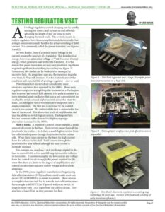
www.electricalrebuilders.org Il voltage regulators control charging rate by rapidly turning the rotor’s field current on and off while adjusting the length of the “on” time to meet changing electrical loads. The control circuits in today’s regulators have become sophisticated electronically, but a single component usually handles the actual switching of field current. It is commonly called the power transistor (see Figures land 2). As with diodes, there is a certain loss of voltage as the current crosses the junction of a transistor. This lost electrical energy, known as saturation voltage or Vsat, becomes thermal energy, which generates heat within the transistor. It is the reason that power transistors on very early electronic regulators required significant heat sinking for cooling (see Figure 3). Transistors, like diodes can be weakened or damaged by excessive heat. As a regulator ages and the transistor degrades over time, its Vsat will increase. It is the best indicator of the condition and expected life of a voltage regulator — new or used. Power transistors have evolved considerably since electronic regulators first appeared in the 1960’s. Those early regulators employed a single bi-polar transistor or a Darlington Pair to power and switch field current. A bi-polar transistor is a three-terminal semi-conductor that uses a low current input on one lead to switch a much higher current across the other two leads. A Darlington Pair is two transistors integrated into a single component. ‘The first one is switched by the control circuit’s low current. The emitter of the first is connected to the base of the second. This allows two levels of amplification and thus the ability to switch higher current. Darlington Pairs became common as the demand for higher amperage alternators increased in the 1970’s. How it works: A regulator’s control circuit supplies a small amount of current to the base. That current passes through the junction to the emitter. As it does, a much higher current from the collector also passes through the junction to the emitter side. When there is no current on the base, the high current from the collector is blocked. Total current through the junction is the sum of both although the base current is normally minimal. For example, we could use 1 mA (milliamp) applied to the base to control 1000 mA or one full amp between the collector to the emitter. Transistors amplify the low current and voltage from the control circuit to supply the power required for the rotor But there are limits to the degree of amplification and control circuits must function on low voltage and very little amperage. In the 1990’s, most regulator manufacturers began using field effect transistors (FETs) and later metal-oxide semi-con- ductor FETs (MOSFETs) as power transistors. These devices accomplish the same task but in a much more efficient manner. For example, a MOSFET (see Figure 4) today can switch 30 amps or more with 1 mA input from the control circuit. They also have a lower Vsat, so they generate less heat. BY GENE KAISER Figure 1 – This Ford regulator uses a large 30 amp bi-polar transistor mounted on a heat sink. Figure 2 – This regulator employs two field effect transistors in parallel. Figure 3 – This Bosch electronic regulator was cutting edge technology 50 years ago. The size of its heat sink is telling of early transistor efficiency. An ERA Publication. ©2016, Electrical Rebuilder’s Association. All rights reserved. No portion of the guide may be reproduced in Page 1 any way, or stored in any electronic retrieval system without the prior written consent of the Electrical Rebuilder’s Association. ELECTRICAL REBUILDER’S ASSOCIATION — Technical Document CS201612B www.electricalrebuilders.org TESTING REGULATOR VSAT Figure 4 – These are 30 amp MOSFETs. Figure 5 – The regulator tester activates the 22-SI regulator’s power transistor. The power supply passes 7 amps of current across the transistor’s junction. The DVM measures Vsat. ape voLnn® Figure 6 – Here we test a used Denso regulator, again using 7 amps. Vsat seems high at 1v. Testing Vsat: Many rebuilders choose to simply replace all regulators with new product to avoid potential warranty returns. Others may base reclaim decisions on cosmetics and functionality testing – operating the used regulator on a tester or as part of the alternator on a test bench. Sometimes you find yourself in a position where you have no choice but re-use a regulator, assuming it functions properly. Yet we have all experienced warranties caused by a regulator’s failure. Most of those could probably have been avoided by testing Vsat. To do that you need a constant current DC power supply to simulate a full-fielded rotor’s amperage across the regulator’s power transistor. The cost of a lab quality adjustable power supply is beyond the resources of a small shop. But today, thanks to a growing interest in electronics and Internet shopping, there are many less expensive options available that will allow you to accurately measure the Vsat of nearly any voltage regulator you may encounter. The one that we used for our photos can supply up to 10 amps and was purchased online for $65. There are three steps to measuring Vsat: « First, you must activate the regulator’s control circuit without connecting anything to the field terminal. You can do this with your regulator tester if you have one or with a test lead for the alternator and any 12v DC power source. Once the regulator is energized, the control circuit should apply low current to the power transistor’s base and activate it for testing. ¢ Second, adjust your constant current power supply toa setting that roughly matches the rotor. We used 7 amps here to test a 22-SI regulator (see Figure 5). Then connect those leads to the regulator’s field terminal and the controlled source on the regulator, which is ground here because it is A-circuit. Be sure that you observe correct polarity for the field connection! In the case of B circuit regulators, connect the positive lead to the field terminal and the negative lead to regulator B+. Do not become concerned about creating a short circuit with the regulator tester’s B+ and ground connections – so long as the tester’s field lead is not used. e Third, connect an accurate voltmeter to the regulator in parallel with the power supply. The voltage reading will be the regulator’s Vsat. We also tested a used Denso SC regulator (see Figures 6 and 7) that had been functioning perfectly but the core it was removed from showed obvious signs of having been overheated . Transistors are temperature sensitive and Vsat will increase as the regulator warms itself up, but that could take too long to make the test practical. A simple way to warm it up quickly is a heat gun or hair dryer. Just be careful that you do not apply too much heat. A temperature of 100 C or 210 F is safe. We monitored the regula- tor’s temperature using an infrared thermometer and suggest you do the same. In our testing, a heat gun on low setting warmed it to that temperature in just a few seconds. You can see the dramatic increase in Vsat in the second photo. Then we tested a new regulator of the same part number to get a comparison between a new power transistor and the question- able used one (see Figures 8 and 9). As you can see, there was a significant difference. An ERA Publication. ©2016, Electrical Rebuilder’s Association. All rights reserved. No portion of the guide may be reproduced in Page 2 any way, or stored in any electronic retrieval system without the prior written consent of the Electrical Rebuilder’s Association.