
Cadillac 1926
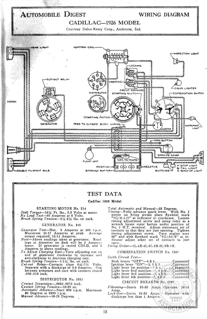
AUTOMOBILE DIGEST IQMITPIOM COW PoC UTESUT BELAY LE AEA FLOAT UNIT POSITIVE BYORAGT BATTIANY WIRING DIAGRAM CADILLAC—1926 MODEL Courtesy Delco-Remy Corp., Anderson, Ind. Dh Caeicanesg AAROUIY SREAKE! STARTING Seton { EGATIVE Switches TEST DATA Cadillac 1926 Model STARTING MOTOR No. 314 Stall Torque—18% Ft. ths., 3.2 Volts at motor. No Load Test—-60 Amperes at 6 Volts. Brush Spring Tension—24-2% lbs. on each. GENERATOR No. 315 Generatoy Test—Hot. 2 Amperes at 500 r.p.m. Maximum 15-17 Amperes at peak. Average output required, 12-14 Amperes. Note—Above readings taken at generator. Read- ings at Ammeter on dash will be 2 Amperes lower. If generator is tested COLD, add 2 Amperes to above readings. To Adjust Charging Rate Tarn adjusting nut on end of. generator
Cadillac 1924
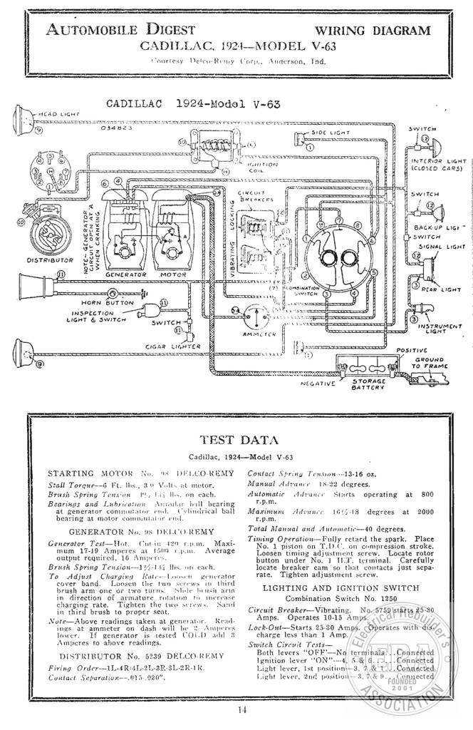
AUTOMOBILE DIGEST WIRING DIAGRAM CADILLAC, 1924_-MODEL V-63 Courtesy Detcu-Remy Corp. Aucterson, Ind. CADILLAC 1924-Hodel vV-63 Rane ; RD — @ att janetc semecenent |] i t | } ee os t ~— naan! at LEAs crmocisem, || q 2) y @ i ” Wr TION BE i INTERIOR LIGHT com yee CARS) | Cig UT { = AH We swites Bararces ? ‘ : @ ape BACKUP LIGt ~ SWwitCaA SIGNAL LIGHT LOCKING NOTE~ GDNERATOR CIRCUIT OPEN ATA WHEN CRANKING, VIBRATING SLI ye mn HORN BUTTON INSPECTION He LIGHT & Switen el 4 SS oer swine – A INSTRUMENT Ja) = LIGHT CIGAR LIGNTER By Si prep mn mm 7 STORAGE NEGATIVE Sati BATTERY a TR A aL A SRT
1959 Chevrolet Air Conditioning
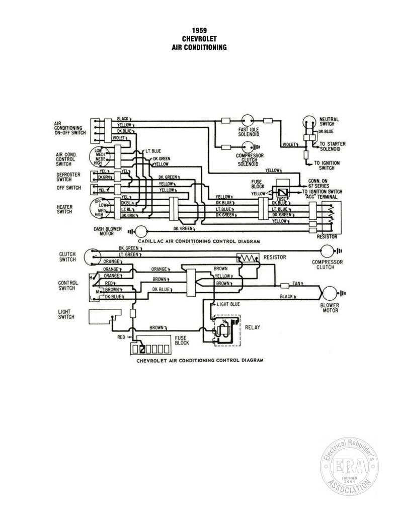
1959 CHEVROLET AIR CONDITIONING SLAC NEUTRAL AIR i C3 = ¢) CONDITIONING E | ua —~ SWITCH ON-OFF SWITCH | ef FAST IDLE Pook. BLUE SOLENOID re an) VIOLET TO STARTER on = 6») ue OLENOID CONTROL ro COMPRESSOR SWITCH Z| a SOLENGI TOIGNITION ( | DEFROSTER | “Txcmn| [| LLL Dc GREEN anol 7 TTT veuow, 7 pel bas sl ona FF — 19 icuion swrren om Ly Tt] ov in “ACC” TERMINAL carer FN foxes 11 OK8 ox BL HEATER | feta gf |} | | trove ar. Cs = DASH BLOWER DK. GREEN CADILLAC AIR CONDITIONING CONTROL DIAGRAM CLUTCH e T GREEN fi [ts RESISTOR SWITCH ee COMPRESSOR URA ); CONTROL A 0 BROWN a Tmowny
1959 Cadillac Trunk Lock
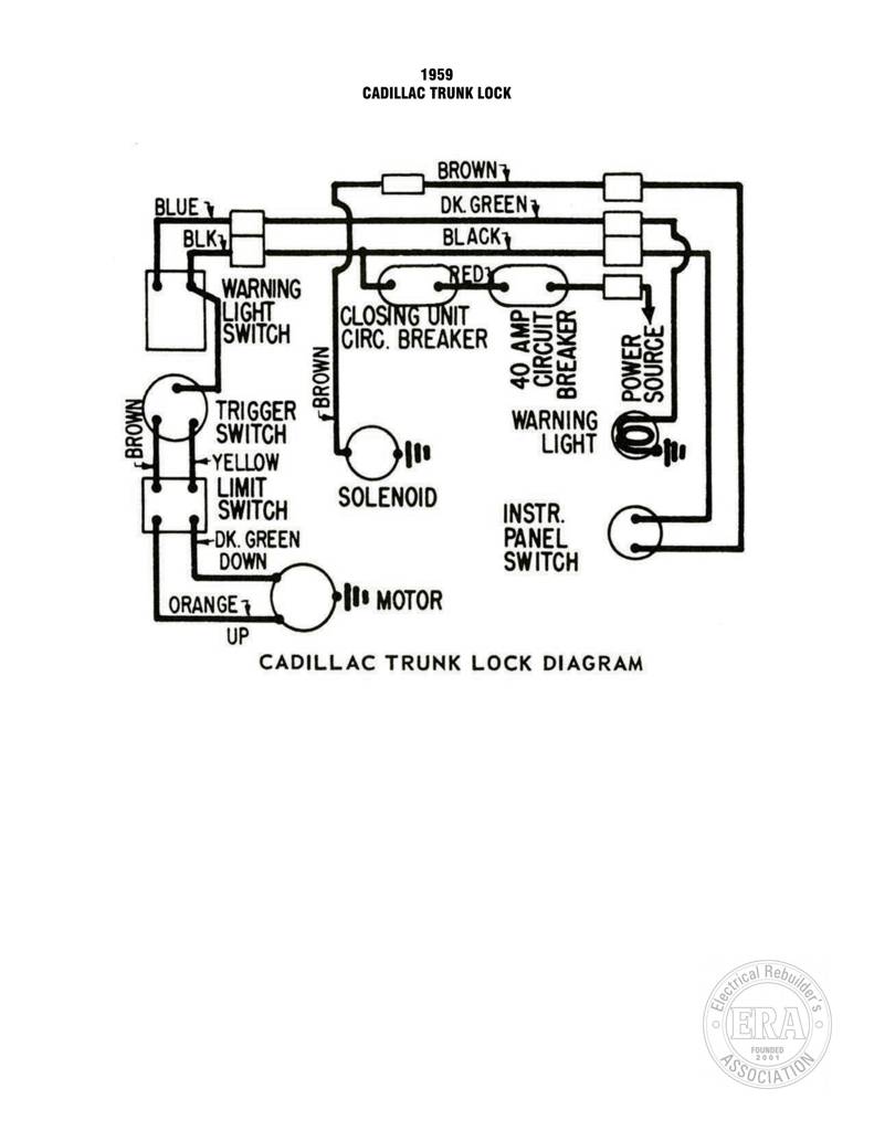
CADILLAC TRUNK LOCK BROWN L_! BLUE —_— warnne f Se SR Or LIGHT. JOLOSING UNIT. =e SWITCH _JCIRC. BREAKER Saxe ty 3 esz 32 oe fea) aa = TRIGGER WARNING d SWITCH zs ni YELLOM (>i ale SS SWITCH SOLENOID = nstR as ai PANEL SWITCH It MOTOR gener TRUNK LOCK DIAGRAM
1959 Cadillac
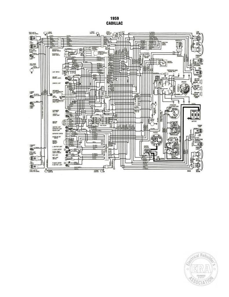
1959 CADILLAC Bo ih = wr ie: 7 set | pilin: aCe ie eet a”, ex os ear Poe rH or mths ETT : SFY we ss | ASS | Sree ee i dee eee all Lf _ a S et — | SSE eeeeeee8 loom Th ae ree! hii ee = ® —— SS i H ok Is = if | _——4 [J mm Sp
1959 Cadillac Door Locks
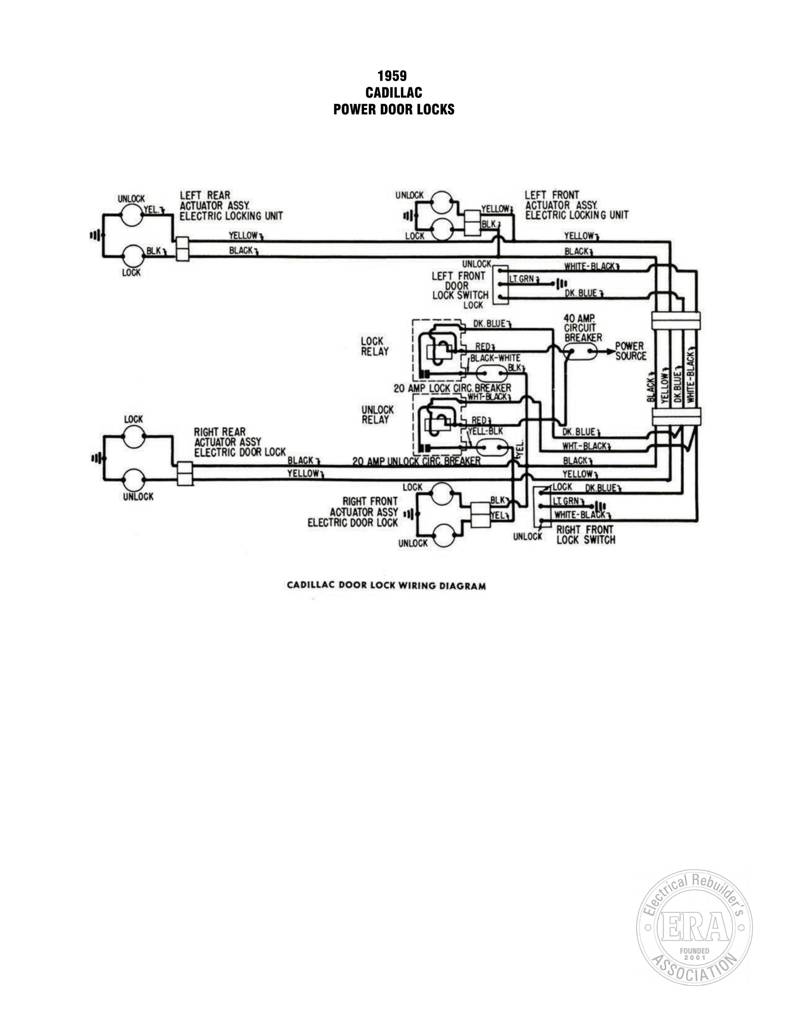
1959 CADILLAC POWER DOOR LOCKS LEFT REAR UNLOCK LEFT SL Uy ety ACTUATOR ASSY € } veuow, ACTUATOR A (EEL ELECTRIC LOCKING UNIT al LAR ELECTRIC LOCKING UNIT ) pal? YELLOW LOCK PY | YELLOW s = UNLOCK i ~ iol ir = Lock SWITCH | POWER relay 1 (5 BLACK WATE PS source § he =I 20 AMP_LOC CK CIRC. 8 BREAKER | Jaye rT Pe Fo UNLOCK Lo ra pas eee ——— OK. BLUE MI / DN Mal elaf { } RIGHT ba ACTUATOR ASSY 1 ELECTRIC DOOR LOCK – BLACK D AMP UN | hae LOCK UNLOCK RIGHT FRONT =e ACTUATOR ASSY 14} ELECTRIC DOOR LOCK Tar: | | EL. 0 — RIGHT FRONT UNLOCK UNLOCK LOCK
1959 Autotronic Eye
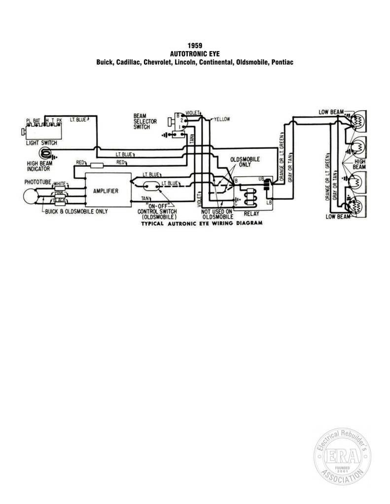
1959 AUTOTRONIC EYE Buick, Cadillac, Chevrolet, Lincoln, Continental, Oldsmobile, Pontiac VIOLET, LOW BEAM; PL BAT JH T PK LT. BLUE a H YELLOW A ANS) Ii 7] Fre LIGHT SWITCH + w A) S,. RED 2 » Tat HIGH BEAM — S ts INDICATOR MY 8 S \ BEAM 5 = =) PHOTOTUBE wut o% BE ly, Q 5 . €) bu, *d:SC«CAMPLIFIER -| Zi-1 [ ni! a Ai: = S ml — ON- OFF f 52) BUICK & OLDSMOBILE ONLY CONTROL SWITCH NOT USED ON < (OLDSMOBILE ) OLDSMOBILE TYPICAL AUTRONIC EYE WIRING DIAGRAM
Cadillac Series 341 341-A 3-00001 UP
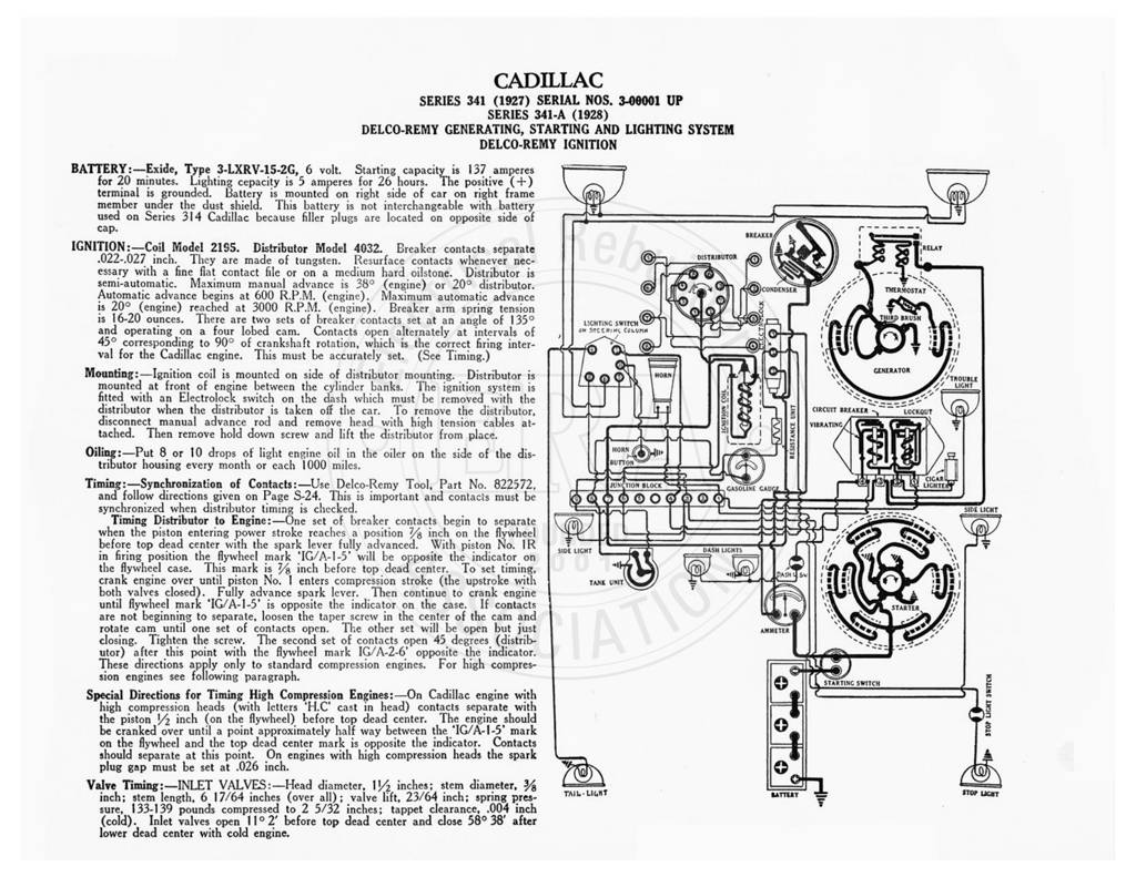
CADILLAC SERIES 341 (1927) SERIAL NOS. 3-06001 UP SERIES 341-A (1928) DELCO-REMY GENERATING, STARTING AND LIGHTING SYSTEM DELCO-REMY IGNITION BATTERY:—Exide, Type 3-LXRV-15-2G, 6 volt. Starting capacity is 137 amperes for 20 minutes. Lighting cepacity is 5 amperes for 26 hours. The positive (+) terminal is grounded. Battery is mounted on right side of car on right frame member under the dust shield. This battery is not interchangeable with battery used on Series 314 Cadillac because filler plugs are located on opposite side of cap. IGNITION: —Coil Model 21$5. Distributor Model 4032. Breaker contacts separate -022-.027 inch. They are made of tungsten. Resurface contacts whenever nec- essary with a fine flat contact file or on a medium hard oilstone. Distributor is
Cadillac Series 341-B
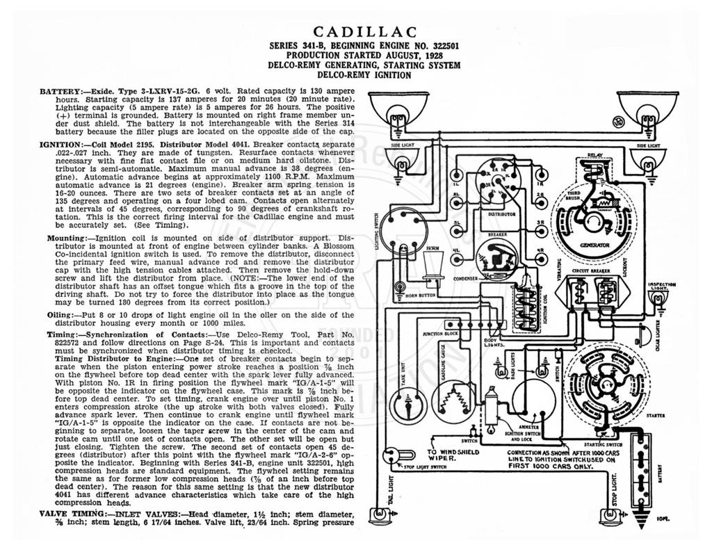
CADILLAC SERIES 341-B, BEGINNING ENGINE NO. 322501 PRODUCTION STARTED AUGUST, 1928 DELCO-REMY GENERATING, STARTING SYSTEM DELCO-REMY IGNITION BATTERY:—Exide. Type 3-LXRV-15-2G. 6 volt. Rated capacity is 130 ampere — hours. Starting capacity is 137 amperes for 20 minutes (20 minute rate). Lighting capacity (5 ampere rate) is 5 amperes for 26 hours. The positive (+) terminal is grounded. Battery is mounted on right frame member un- , ao der dust shield. The battery is not interchangeable with the Series 314 battery because the filler plugs are located on the opposite side of the cap. IGNITION :—Coil Model 2195. Distributor Model 4041. Breaker contacts separate .022-.027 inch. They are made of tungsten. Resurface contacts whenever necessary with fine flat contact file or
Cadillac Model 314 141,001 UP
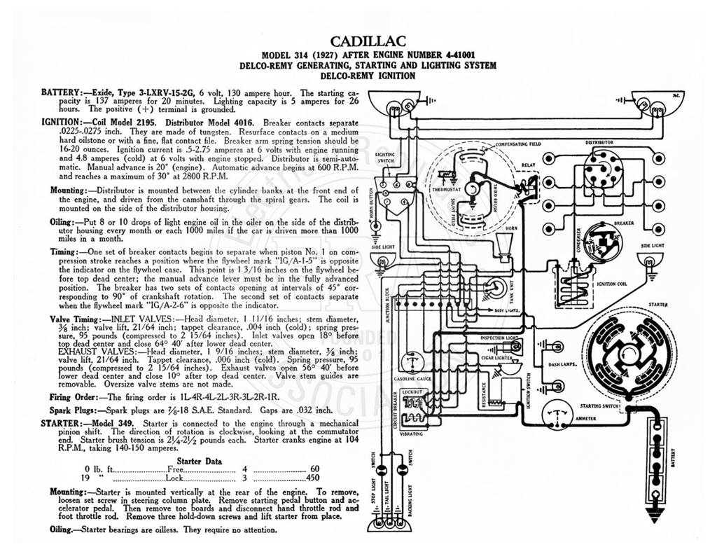
CADILLAC MODEL 314 (1927) AFTER ENGINE NUMBER 4-41001 DELCO-REMY GENERATING, STARTING AND LIGHTING SYSTEM DELCO-REMY IGNITION BATTERY:—Exide, Type 3-LXRV-15-2G, 6 volt, 130 ampere hour. The starting ca- city is 137 amperes for 20 minutes. Lighting capacity is 5 amperes for 26 [1 tl : fous, The positive (+) terminal is crounted @sS Qe IGNITION:—Coil Model 2195. Distributor Model 4016. Breaker contacts separate ihe -0225-.0275 inch. They are made of tungsten. Resurface contacts on a medium al hard oilstone or with a fine, flat contact file. Breaker arm spring tension should be ee COMP CHSATING FIELD 16-20 ounces. Ignition current is .5-2.75 amperes at 6 volts with engine running A De GN and 4.8 amperes (cold) at 6 volts with engine